SUNWAY TG 485 800V TE (S64)
SUNWAY TG 610 800V TE (S64)
SUNWAY TG 730 800V TE (S64)
SUNWAY TG 750 1000V TE (S64)
SUNWAY TG 760 1000V TE (S64)
SUNWAY TG 610 1000V TE/TE (S62)
SUNWAY TG 1200 1000V TE/TE (S62)
SUNWAY TG 900 1500V TE/TE (S62)
SUNWAY TG 1800 1500V TE/TE (S62)
R400 - R500 - R800 - R1000 - R1200 - R1500TLI - R2000TLI - R2250TLI - R2500TLI - R3000TLI - R3750TLI - R4000TLI - R4500TLI - R5000TLI - R6000TL - R6800TL - R7500TL - R5515TL - R6615TL - R7715TL - R8815TL - R10015TL - R11015TL - R3015TL - R12715TL - R14015TL - R15015TL - R18615TL
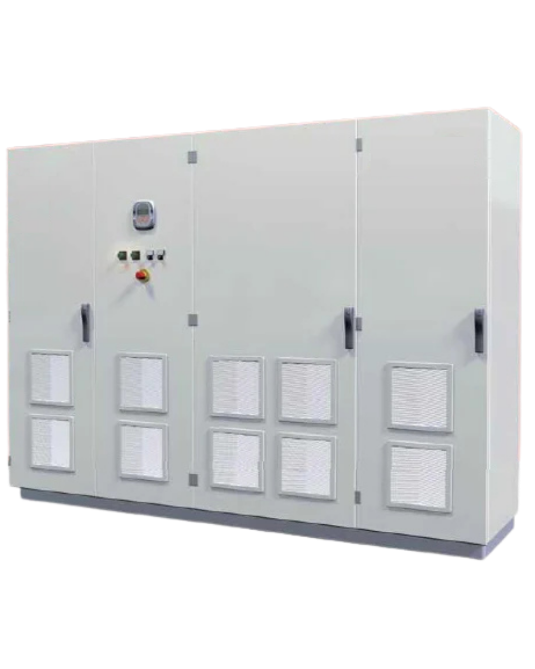
SANTERNO SUNWAY TG- TG TE
Listed below are the requirements for initial action on a failed inverter. Before proceeding with any operation: A) Verify that the model is correct; B) Carefully follow all instructions provided in the manufacturer’s operation and maintenance manual; C) Ensure that the intervention is carried out by trained personnel; D) Since this is a photovoltaic inverter with a DC input that is always live, strictly observe all applicable safety regulations.
Alarms, Errors and Warnings
|
Codice
|
Allarme
|
Descrizione
|
Possibile soluzione
|
|---|---|---|---|
|
A040 |
User Alarm |
User-generated alarm |
Reset the alarm: send a RESET command. |
|
A041 |
IGBT FAULT Side A |
Generic A-side IGBT Hardware Alarm |
1. Reset the alarm: send a RESET command. |
|
A043 |
FALSE SOFTWARE INTERRUPT |
Control Board Malfunction |
Contact STI REPAIR Service |
|
A044 |
OVERVIEW |
Overcurrent Software |
Contact STI REPAIR Service |
|
A045 |
Fault bypass |
Precharge By-Pass Fault |
1. Reset the alarm: send a RESET command. |
|
A046 |
Fault connector |
Precharge By-Pass Connector Fault |
1. Reset the alarm: send a RESET command. |
|
A047 |
Undervoltage |
Bus-Dc voltage less than Vdc_min |
1. Check the value of the measured Bus-Dc voltage M010. |
|
A048 |
Overvoltage |
Bus-Dc (DC link circuit) voltage has reached a |
1. Check the value of the measured Bus-Dc voltage M010. |
|
A049 |
RAM FAULT |
RAM DSP Texas inconsistent |
Contact STI REPAIR Service |
|
A050 |
IGBT FAULT A |
Hardware Fault from A-side IGBT Converter |
1. Reset the alarm: send a RESET command. |
|
A051 |
Overcurrent |
Overcurrent A-side Hardware |
1. Check the correct sizing of the inverter with respect to the |
|
A052 |
I INV Asymmetrical |
Hardware Fault: Asymmetry in inverter output currents. |
1. Reset the alarm: send a RESET command. |
|
A053 |
NOT PWONA |
Hardware Fault: Unable to turn on IGBT A |
1. Reset the alarm: send a RESET command. |
|
A054 |
TLP or TLext FAULT |
Status of one or both parallel and network interface contactors not |
1. Check the condition of the wiring harnesses. |
|
A055 |
TLext NOT OPEN |
External contactor closed |
1. Check the condition of the external contactor. |
|
A056 |
External open contactor |
Measured overvoltage between phases ST |
1. Check the condition of the network interface contactor |
|
A057 |
TLP NOT OPEN. |
TLP closed |
1. Check the condition of the TLP contactor |
|
A058 |
TLP NOT CLOSED. |
TLP open |
1. Check the condition of the TLP contactor and the wiring of the |
|
A061÷A062 |
Watchdog line |
A061: Triggered Watchdog Serial Line 0 |
1. Verify the serial connection. |
|
A064 |
Field Switch |
Open field switch |
1. Check the closure of the field switch at the front of the panel. |
|
A065 |
Mains Switch |
Mains switch open |
i |
|
A066 |
Input Current |
Detects a current on Ref input less than 4 mA, while the range |
Interrupted input sensor wiring. |
|
A067 |
Overtemperature |
CPU Temperature Higher than Maximum Allowed |
1. Reset the alarm: send a RESET command. |
|
A068 |
PV KO insulation |
PV field insulation KO |
1. Check the galvanic isolation of the PV array. |
|
A069 |
Download PAR KO |
Error during parameter download operation from |
Repeat the Download operation. |
|
A070 |
Download PAR KO |
Error during parameter download operation from |
Repeat the Download operation. |
|
A071 |
1ms INTERRUPT OVERTIME |
Control Board Malfunction |
Contact STI REPAIR Service |
|
A074 |
Overload |
Triggered Inverter thermal protection |
Check the current delivered by the inverter under normal |
|
A081 |
... |
Display/keyboard malfunction. |
1. Check the connection of the display/keyboard cable. |
|
A082 |
TLP NOT CLOSED2 |
TLP/KM1open |
1. Check the condition of TLP contactor and wiring of |
|
A083 |
Fault Fans |
Fan alarm |
Replace the failed fan. |
|
A084 |
Fault 2nd Sensor |
Heatsink overtemperature protection trip due |
1. Reset the alarm: send a RESET command. |
|
A093 |
Preload: |
ByPass relay open |
1. Reset the alarm: send a RESET command. |
|
A094 |
Overtemperature |
Detected IGBT heatsink temperature too high |
1. Reset the alarm: send a RESET command. |
|
A106 TO A109 |
Input current |
Detected current on Analog inputs less than 4 mA, while |
1. Check the wiring of the input sensor. |
|
A043 A063 |
Malfunction |
Hardware Card Malfunction |
1. Reset the alarm. |