
R400 - R500 - R800 - R1000
R1200 - R1500TLI - R2000TLI
R2250TLI - R2500TLI - R3000TLI
R3750TLI - R4000TLI - R4500TLI
R5000TLI - R6000TL - R6800TL
R7500TL - R5515TL - R6615TL
R7715TL - R8815TL - R10015TL
R11015TL - R3015TL - R12715TL
R14015TL - R15015TL - R18615TL
R400 - R500 - R800 - R1000 - R1200 - R1500TLI - R2000TLI - R2250TLI - R2500TLI - R3000TLI - R3750TLI - R4000TLI - R4500TLI - R5000TLI - R6000TL - R6800TL - R7500TL - R5515TL - R6615TL - R7715TL - R8815TL - R10015TL - R11015TL - R3015TL - R12715TL - R14015TL - R15015TL - R18615TL
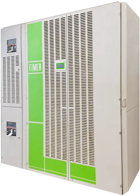
FIMER R SERIES
Listed below are the requirements for initial action on a failed inverter. Before proceeding with any operation: A) Verify that the model is correct; B) Carefully follow all instructions provided in the manufacturer’s operation and maintenance manual; C) Ensure that the intervention is carried out by trained personnel; D) Since this is a photovoltaic inverter with a DC input that is always live, strictly observe all applicable safety regulations.
Alarms, Errors and Warnings
Codice |
Allarme |
Descrizione |
Possibile soluzione |
|---|---|---|---|
|
11 |
Voltage near the limit |
Loose tension is close to the set limit |
Check the values of the three phases: if they are close to the limit even when the inverter is off you need to check the transformer, if the phase values are close to the limit only when the inverter is running contact STI REPAIR service |
|
12 |
Degraded service |
A module failed to activate after at least three attempts. |
If the problem persists, contact STI REPAIR service. |
|
13 |
Loss of DC insulation |
An inverter insulation loss has been detected. |
Check the fuse of the grounding kit and replace it if it is blown. |
|
14 |
Modxxx AD Auto Zero KO |
The module motherboard has a problem in resetting the parameters |
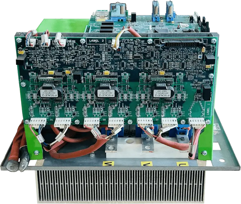
Check all wire connections on the electronic boards of the modules. |
|
15 |
Modxxx Alim KO 24V |
Lack of 24 V DC from the module's DC stack |
Check the status of VAUX auxiliary switches (they must be closed) or the presence of the auxiliary line fed by the auxiliary transformer ***. |
|
16 |
Modxxx Capacitor KO |
The module motherboard received an incorrect voltage value |
Check all wire connections on the electronic boards of the modules. |
|
17 |
Modxx no calibration |
Problems with the calibration of the module motherboard |
Contact STI REPAIR Service |
|
18 |
Modxxx No configuration |
No module configuration |
Contact STI REPAIR Service |
|
19 |
Eeprom Modxxx Error |
Problems with motherboard eprom |
Contact STI REPAIR Service |
|
20 |
Modxxx Overcurrent R |
Overcurrent in the first phase |
Check the circuit breaker connections of the module in error but only to inform the STI REPAIR service of its main switchboard. |
|
21 |
Modxxx Overcurrent S |
Overcurrent in the second phase |
Check the circuit breaker connections of the module in error but only to inform the STI REPAIR service of its main switchboard. |
|
22 |
Modxxx Overcurrent T |
Overcurrent in the third phase |
Check the circuit breaker connections of the module in error but only to inform the STI REPAIR service of its main switchboard. |
|
23 |
Modxxx Overtemperature Mag1 |
Magnet (transformer) overtemperature |
Check the connection labeled "J17" on the unit control board (not present on the R15015TL inverter or otherwise in transformerless inverters). |
|
24 |
Modxxx Overtemperature Mag2 |
Magnet overtemperature (inductance) |
Check the connection marked "J16" on the unit control board. |
|
25 |
Modxxx RS Overvoltage |
Measured overvoltage between phases RS |
Check the value of the three phases: it should be around 550Vac. |
|
26 |
Modxxx Overvoltage ST |
Measured overvoltage between phases ST |
Check the value of the three phases: it should be around 550Vac. |
|
27 |
Modxxx Overvoltage TR |
Measured overvoltage between phases TR |
Check the value of the three phases: it should be around 550Vac. |
|
28 |
Modxxx UDC Overvoltage |
Overvoltage in DC voltage |
Check the VDC voltage value and if it is within the normal range (around 850-1320 Vdc) try restarting the inverter. |
|
29 |
Modxxx Shutdown KO |
Problems in driving the module's DC stack |
Check the presence of the auxiliary line and/or DC pack operation of the module: if both are ok contact STI REPAIR service |
|
30 |
Modxxx Ramp KO |
Module fails to finish the startup procedure: problem reading values |
Check all wire connections on the electronic boards of the modules. |
|
31 |
Modxxx IGBT KO |
Module does not start due to problems in IGBT drivers: general alarm |
Check all wire connections on the electronic boards of the modules. |
|
32 |
Modxxx has lost synchronicity |
Connection problem between the Supervisor and the module motherboard. |
Check the connection between the modules electrical board and the supervisor, the cable whose connection check is the multicolor flat cable. |
|
33 |
Modxxx Overtemperature |
Module temperature limit |
The IGBT module has reached the temperature limit. |
|
34 |
Modxxx undervoltage RS |
Undervoltage measured between phases RS |
Check the value of the three phases: it should be around 550Vac. |
|
35 |
Modxxx undervoltage ST |
Undervoltage measured between ST phases |
Check the value of the three phases: it should be around 550Vac. |
|
36 |
Modxxx undervoltage TR |
Undervoltage measured between phases TR |
Check the value of the three phases: it should be around 550Vac. |